1
25
submitted 1 week ago by [email protected] to c/[email protected]

I have a 3d printer in my car powered by a bluetti eb3a. The bluetti is charged by the 12v outlet in my car while driving. I have a 24v solar panel i want to mount to the roof of the car. My bluetti has only one dc 7909 input. So got a a Y splitter to combine power from the car and panel. But when plug it into the car outlet that turns off when i turn off the car, the solar panel turns on the stereo. Thats not the case with the outlets that are always on. I am worried that i will danage the car electrical system from a 24v solar panel flowing electricity back into the car?

2
9
submitted 2 weeks ago* (last edited 2 weeks ago) by [email protected] to c/[email protected]

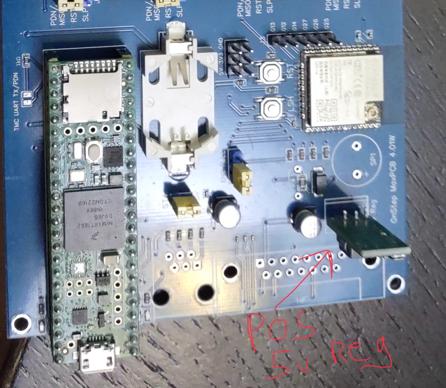
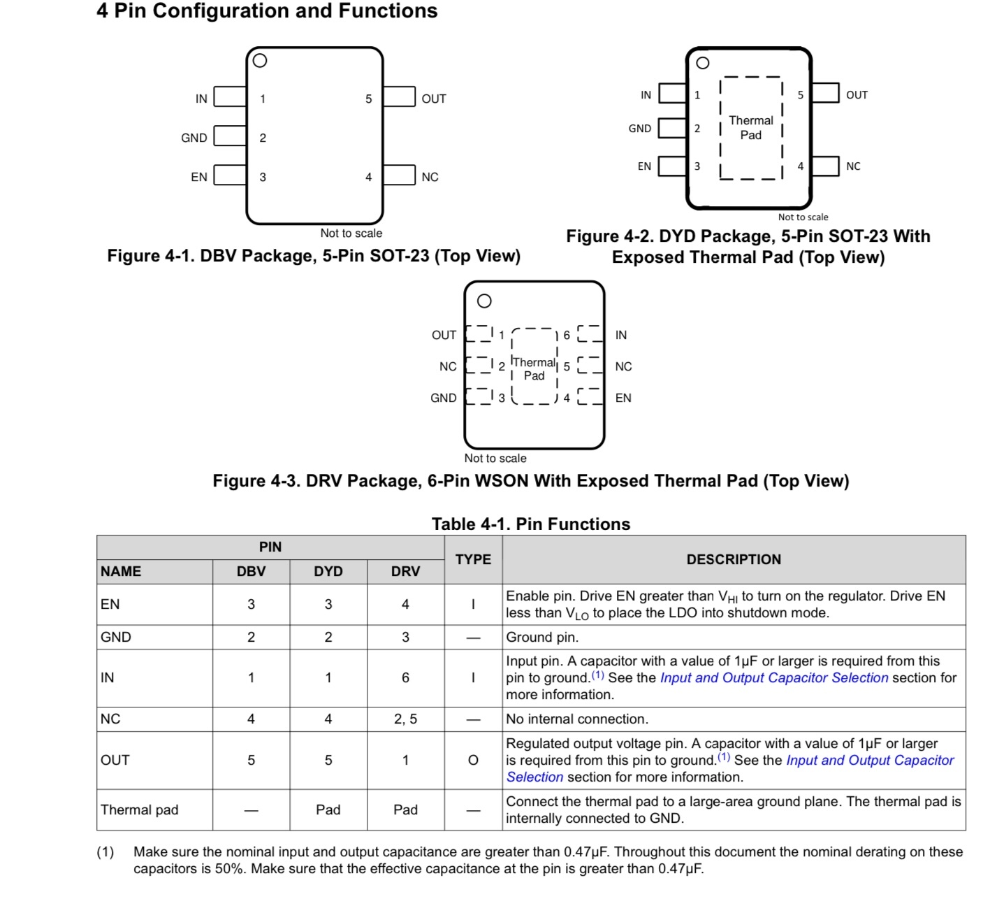
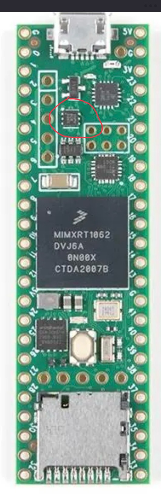
I have a project that is using a Teensy 4.1, the cheep 5v regulator I was using in the project let the magic smoke out for no good reason. I replaced that but now the Teensy boots and runs for about a min then quits. There is a TLV75733P power IC that is supplying the 3v3 and it gets hot then quits supplying power. Since that IC is $0.46 vs a new Teensy 4.1 ~ $40 I want to try and replace it. I have done a bit of SMD work but not tried to remove a tiny chip with a GND pad before so I’m looking for any tips. The PCB of the Teensy has header pins so I can’t really get good contact to a hot plate to preheat the board.

3
30
submitted 2 weeks ago* (last edited 2 weeks ago) by [email protected] to c/[email protected]

I am working on a WLED project, using a esp32 in a 3d printed enclosere. But my dad says that i can't install it because it is not UL listed. He is worried if the house burns down, the insurance company won't insure it due to diy electronics possibly starting a fire. What am i to do, i am not developing a project to sell?

4
9
submitted 2 weeks ago by [email protected] to c/[email protected]

Hello !

I recently 3dprinted a train whistle that usually works with a mouthpiece. It works by simply blowing air in it.

However, I would like to convert it to a whistle for my bike. For that I would need a system that could blow air in it, instead of myself, with the press of a button.

Any idea on what i could start with to build that ? It would be best if the circuitry was quite compact too.

Thanks !

5
14
submitted 3 weeks ago by [email protected] to c/[email protected]

I want to store a battery powered device long term (decades) as a reference article, it will never be switched on or charged again. The problem is that it contains a small LiPo battery that will be very hard to remove.

Is there likely to be any significant risk I need to worry about? Once depleted will the battery be relatively inert?

6
23
submitted 3 weeks ago* (last edited 3 weeks ago) by [email protected] to c/[email protected]

EDIT: Thanks everyone for you help, that has been very instructive. I think I just have a very poor quality cable adapter. Given that Blueretro is mostly an opensource DIY project, I’ll make a cable adapter myself instead of trying to fix what would obviously not function properly.

Hi everyone,

First of all let me say that I’m a total noob in electronics (I really only know the basics) and I’m facing an issue that I really don’t know how to tackle.

I have bought a Blueretro NES adapter on Aliexpress (this one) and it does behave erratically when powered by the console alone (Bluetooth not working, LED indicator down, random outputs to the console).

When I’m powering via USB, everything function properly.

So I guessed that I might have a voltage issue on the NES side. I tested mine and make a few friend test theirs (5 in total including mine) and the result is still the same: the controller ports outputs between 4.6 and 4.8V instead of 5V.

The Blueretro itself apparently uses an AMS1117 (picture here) which, from my understanding, is stepping down 5V to 3.3V (wild guess, I don’t really know what it does, just quickly read the datasheet).

So, sorry for the long intro, here are my questions:

  • Is it wise to try to step up the voltage from the NES to the Blueretro from 4.6V to 5V? How would it be possible? Is it even possible?
  • Given that the Blueretro is taking 3.3V apparently, is it possible to step down from 4.6V to 3.3V instead? Is it wiser than stepping up?

Thanks in advance and sorry for the long post :)

7
10
submitted 3 weeks ago* (last edited 3 weeks ago) by [email protected] to c/[email protected]

So my wife cracked the screen of her Playdate console. I got a replacement memory LCD (Sharp LS027B7DH01A), but the LCD is mounted with optically clear adhesive directly to a piece of glass which is adhered around the edges to the console’s faceplate.

The glass measures 65.15x41.64mm by 0.65mm thick. Definitely not a standard size. I can’t find anywhere to buy glass so thin and so large.

My first thought was to cut a phone screen protector down to size with a glass cutter. My first attempt failed because the screen protector I bought was actually coated in plastic on both sides. Even if I got a straight cut, I couldn’t find a way to slice through the plastic layers cleanly.

Any ideas on where to find cuttable glass sheets this thin? I could try more screen protectors, but there’s no way to know if they’ll work before buying them.

8
27
submitted 3 weeks ago by [email protected] to c/[email protected]

I came across this today and I thought it might be an incredibly powerful tool. So I was curious to see if anybody in this community has used it yet?

9
9
submitted 3 weeks ago by [email protected] to c/[email protected]

I'm new to electronics and looking to assemble an array of components and tools for working on and designing electronics & circuits. Something immediately apparent is that all of the widely available kits orient you towards working with microcontrollers and SBCs; these kits are cool, but I want to have a halfway decent understanding of the underlying analog components and circuit design before I go digital.

With that in mind, what should I get? If anyone could specify specifics to look into, I'd really appreciate that! Thanks for the help.

Current list

  • A decent breadboard
  • Jumper wires
  • Multimeter
  • Batteries
  • Variable Power Supply?
  • Assorted resistors (1Ω-?)
  • Capacitors (Electrolytic and ceramic?)
  • Various ICs?
  • Transistors?
  • Diodes, probably?
  • Potentiometers
10
19
submitted 4 weeks ago by [email protected] to c/[email protected]

Hi everyone

I've been experimenting with methods of applying etch resist with a laser and dry film. The process is kind of arduous and error prone.

Developing with sodium carbonate solution to clear unexposed etch resist takes long, doesn't work well and if you leave it too long the developed etch resist will break as well.

I use a laser module attached to a 3D printer to draw the PCB (LCB?) on the etch resist. This laser almost instantly solidifies toner for laserprinters and also almost instantly hardens dry film.

Using powdered toner and a laser would be a much quicker way to apply etch resist since the excess can be wiped off and reused easily. The problem is applying a uniform layer of toner.

Suspending toner on the surface of water and hydrodipping the plate seems to work but drying takes too long.

Spray coating could work but is messy.

Isopropyl alcohol softens the toner too much making it impossible to clean the excess off.

I have not tried using a roller or electrostatic application yet but that could work well.

Does any of you have experience with this and have ideas/advice?

11
16
submitted 1 month ago by [email protected] to c/[email protected]

So, I've got a laptop screen that's giving up on me. 2/3 of the screen runs alright but the 1/3 on the left edge is acting weird. Half of the broken section displays an image but the image smudged and weird, while the other half is just dead. I opened it up to see what's up and, lo and behold, a wee tiny capacitor is missing (I know it's a capacitor 'cause I looked of the board marking, C248).

Now I'm wondering, since ordering a single capacitor just for fixing this screen is not worth the effort, can I just... put some solder in there to at least get power to where it needs to go? I know it's definitely not ideal but, this is an ancient laptop. Putting in the effort to fix it perfectly is not exactly a great value proposition. What I want to know most is, will the screen be damaged if I do this, or what could go wrong if I do this?

I'm pretty new to DIY electronics fixing so sorry if this is a stupid question. Thanks in advance y'all. Cheers!

12
7
submitted 1 month ago* (last edited 1 month ago) by [email protected] to c/[email protected]

Does anyone have any advice on routing some high speed signals on flex PCBs? I'm looking at jlcpcb because of the low cost but I'm having difficulty getting impedances to be decent.

My requirements are:

  • 45 ohm single ended impedance (maybe? Def doable)
  • 90 ohm differential impedance (usb spec)
  • 5A current on power pins

But if we look at the capabilities: https://jlcpcb.com/capabilities/flex-pcb-capabilities

  • 2 layer
  • substrate thickness (PI) = 25 um
  • 1 oz pour thickness = 35 um
  • min trace width/spacing = 4/4 mil = 0.101/0.101 mm
  • ε = 3.3

Is this feasible with this stackup? I'd like to do a 1 oz pour because of power traces, but there's also 0.5 oz (18um) and 0.33 oz (12um).

For the differential signals, when I'm doing impedance calculations, I can get to roughly 70 ohms using W=100um, S=200um. I don't think this is good enough. I think I can get away using a 0.33 oz pour but then I'm worried about the power pins.

And for the power traces, I'm needing 2.2mm, which is reasonable for the pins on a USB-C connector. But if I try using the 0.5 oz or 0.33 oz pour, it gets to be 4.2 mm and 6.3 mm, which seems impossible given the pins are tiny and very closely spaced together. Even with vias to the bottom layer, this seems problematic.

Anyone have any advice here? This is just for a hobby project, so I'm really not looking to change fabs because of costs.

13
10
submitted 1 month ago* (last edited 1 month ago) by [email protected] to c/[email protected]

Hy I bought a cheap Yagi wifi antenna need some help cause the previous owner broke it and tried to fix it red neck style... It didn't work ... I hope I would be able to add a picture here is a breaf description anyway it's the cheapest brand you can find online the main element is formed into an oval shaped metal ring and here comes my question where should I solder the middle wire ? On one end ? On the other ? Should I pass it throu the (hollow) metal ring and weld it back to himself ? I have seen people build Yagies with similar ovaly shaped rings and they made the cable pass through half the ring and weld it there the problem is that my ring is shaped exactly like a C it doesn't have a second gap in the middle of the left part ... (Here=>C) English is not my first language hope it's good enough to be understood ask if not 👍🏻

14
22
submitted 1 month ago* (last edited 1 month ago) by [email protected] to c/[email protected]

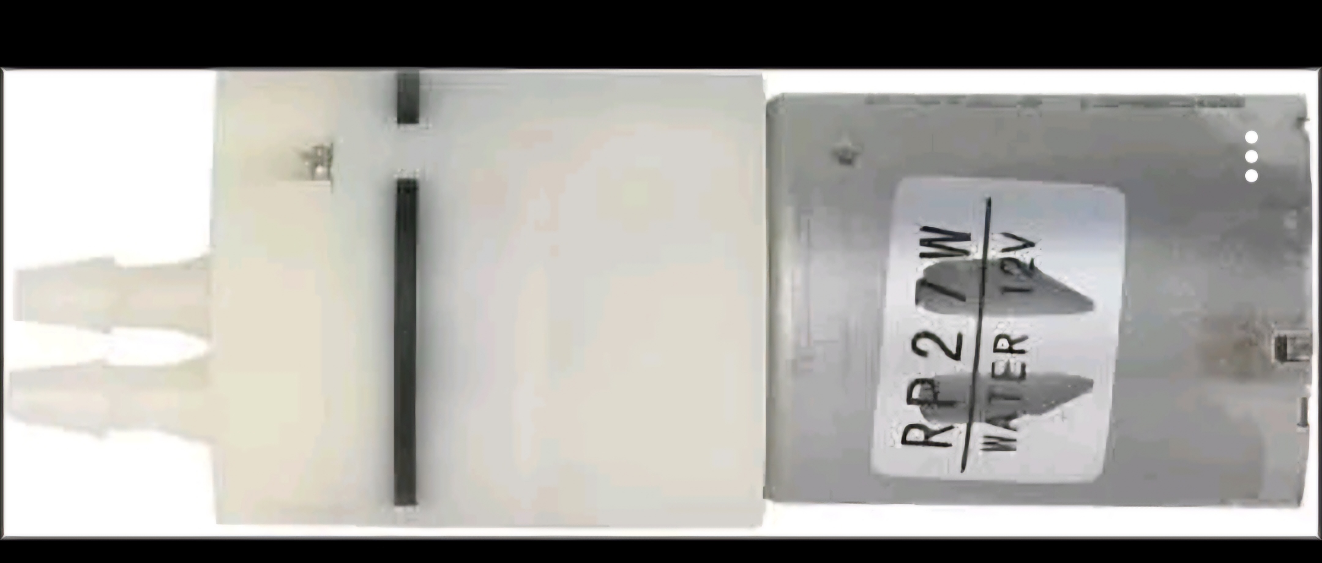
I'm trying to use it as a water pump for my aquarium. I'm using a 6V 4.5AH battery with a DC step up convertor to power the pump. After about 5 minutes it gets really hot. Is this expected?

15
31
submitted 1 month ago by [email protected] to c/[email protected]

Hello, and thank you in advance.

I'm making a privacy friendly "ring" cam/doorbell following this guide: https://tristam.ie/2023/758/ which has been great, but requires running a micro-usb cable down to the doorbell for power. I'm hoping to improve on this by using the existing doorbell power instead.

The problem is that I'm a DIY electronics noob and I can't create a mental model for how it should all work. The picture I attached is my existing doorbell wiring scheme, which is as simple as it comes. I totally get how this works. Pressing the doorbell completes the circuit and makes the bingbongs. But this will have to change so the new door cam gets power full time. Ideally without the chime bingbonging full time.

In addition to the ESP-32CAM, button, ring lights, etc., I also bought these: https://www.amazon.com/dp/B079FJSYGY which I thought might be needed to complete the circuit?

I measured the voltage after the transformer and it was around 18 volts, but maybe this is AC and I want DC?

Generally I don't know where in "the loop" to put things. Also, all the existing components are very far apart from each other, so I would love a solution that doesn't involve running any new wires through the walls.

Any help is appreciated. Thank you!!

xoJimbabwe

16
31
submitted 1 month ago by [email protected] to c/[email protected]

So I used something like these some years ago to recover data off a phone, but I was wondering if the reverse is possible in having a bga soldered adapter with a microsd slot on top. Or if PCBs can even be soldered together like that. I've never actually checked if bga chips have raised pads or something. The purpose would be for rapidly testing custom firmware for shitty old devices that were designed to be replaced without removing the emmc to flash it separately.

17
42
submitted 1 month ago by [email protected] to c/[email protected]

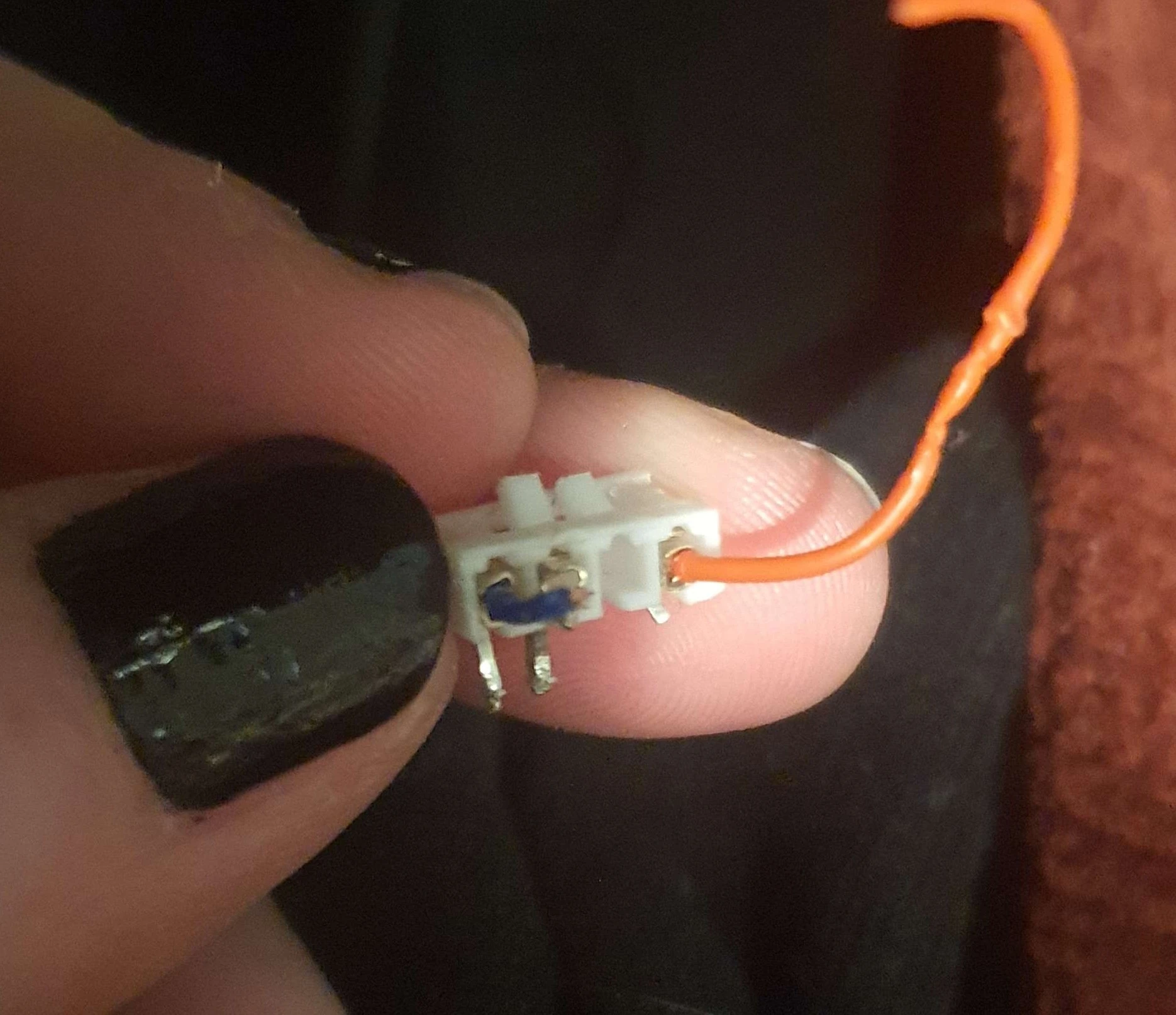
This was a switch that got its wires pulled out. I learned how to desolder today in order to remove it from the little switch board and now there's three holes where this used to be. Does this component have a name, because I'm wondering whether I can just get a replacement one like this. There are lots of tools and supplies at the makerspace I used, but I need to know what I'd be looking for.

Alternatively, what else might I be able to use to do this? I suppose I could just trim and strip the wires and shove those through and solder, but that seems...crude? I don't know. I'd prefer something with pins because I practiced soldering and desoldering using some broken electronics I had, and I'm more confident with pins than something so freeform.

Thanks for your time.

18
19
submitted 2 months ago by [email protected] to c/[email protected]

I am looking for some sort of big programmable buttons. Not sure if something simple exists.

Basically, this is to enhance flow through clinic, looking for a relatively simple solution.

I just want some big battery-powered bluetooth buttons that I can give custom commands in tasker to text tell people to assist with tasks or bring me certain things. I'm not sure if something simple like this exists. (Thinking of like three or four different colored "easy" buttons).

I haven't found anything quite as specific as this, but it's been something nerdy I've been thinking about that would save me time.

19
11
submitted 2 months ago by [email protected] to c/[email protected]

LEDs will conduct more current when they get warmer and differences between individual LEDs mean you cannot easily put them in parallel. A constant current DC supply will be good enough for part of the LEDs but will overload some others. To normalize current a series resistor is used with each individual LED.

Now, those resistors waste a bit of power. Are they really necessary? If you put several LEDs in series the individual differences become negligible at some point and a constant current supply will suffice for several strips of series LEDs in parallel.

How many LEDs would this require? Another possibility would be to have the resistor in series with a strip of LEDs.

I got some LED strips off AliExpress that run on 12V and each individual LED has a resistor in series with it. I believe this to be quite wasteful and it would be better to have several LEDs in series with a current regulator instead. The LEDs will end up in an autonomous greenhouse where power efficiency is important.

20
9
submitted 2 months ago* (last edited 2 months ago) by [email protected] to c/[email protected]

Hello Lemmings, Hope you guys are doing well.

Objective: Open the door automatically through HomeAssistant

My Plan:

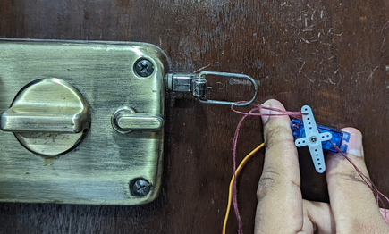
  1. Use an ESP32 and flash ESPhome. Wire up Servo Motor (SG90) with ESP32. Tie a thread on between the Servo Motor Arm and the physical latch (physical latch that I can pull to unlock the door) such that when the servo motor turns from -100 to +100, the latch is being pulled to cause the door to be unlocked.

  2. I am planning to power this using AA Cells + DC DC Boost convertor.

Issue:

  1. How do I mount the Servo Motor on the door?
  2. Is there any other (read better) way to achieve the same result?
  3. Would you recommend any power source other than AA Cells?

Image for reference:

The latch has a keychain-like loop where the thread is tied. To unlock the door manually, I pull the latch towards right (---->) . This action is planned to be automated by Servo Motor.

21
19
submitted 2 months ago by [email protected] to c/[email protected]

This is an idea that entered my mind. The traditional way is applying some etch resist like toner or dry film, etching away the copper and then adding solder mask before populating the board with components.

Can the solder mask be used as etch resist instead? It feels like skipping an unnecessary step in the process. Why isn´t this more common? This way you won´t need the step of removing etch resist only to replace it with a slightly different compound.

22
73
submitted 2 months ago by [email protected] to c/[email protected]

Ever since I've gotten into Retro Computing, I've been confronted about things like soldering, Circuits and Electrics in general... and it has made me want to try experimenting with my own ideas!

That does however mean that im still pretty inexperienced and thusly don't have anything to actually experiment with either.

So what kind of Breadboard Kit will give me the best and most things to start getting into this Hobby?

23
126
Overclocking gone wild (sh.itjust.works)
submitted 2 months ago by [email protected] to c/[email protected]
24
13
submitted 2 months ago by [email protected] to c/[email protected]

It appears to me that UV resin, used for SLA printers should be quite convenient for making PCBs with a laser etcher. You can spread a thin layer of resin on the board and quickly expose it using a laser engraver. It should be most convenient for silkscreen layers that are otherwise difficult to apply.

I think the common method of applying UV mask and spreading it using a piece of plastic sheet is messy and I can never guess how much resin to apply. It's always too much or too little and it's always unevenly spread. And then the UV light exposure is another guessing game.

I have a 500mw 405nm laser module attached to my 3D printer and could easily 'print' some PCB layouts on a thin layer of SLA resin.

Does anyone have experience with this?

25
1
submitted 3 months ago by [email protected] to c/[email protected]

Hello,

I'm creating a BoM for a youth group project. We're planning on building the Electromagnetic Ring Accelerator from Hyperspace Pirate. He's provided the 3d print files, but not the finer details on wire gauge, enamel wire gauge and ball size. I also want to confirm the photoresistor. Are there different photoresistors with with different sensitivities or ranges?

I've included the wip of the BoM.

view more: next ›

Ask Electronics

3139 readers
1 users here now

For questions about component-level electronic circuits, tools and equipment.

Rules

1: Be nice.

2: Be on-topic (eg: Electronic, not electrical).

3: No commercial stuff, buying, selling or valuations.

4: Be safe.


founded 1 year ago
MODERATORS