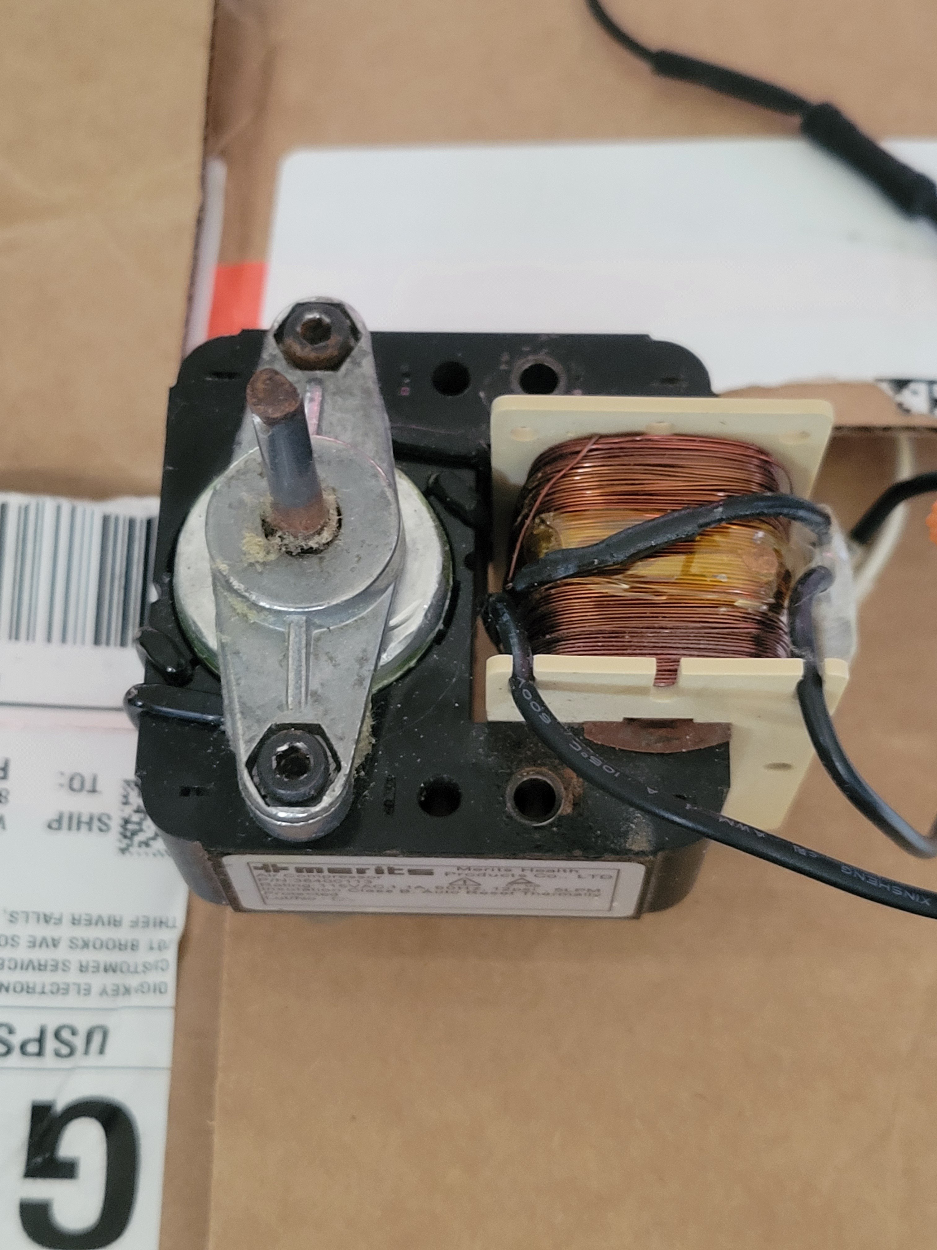
Title pretty much says it all. I'm trying to find a current limiting ballast for a solid state tesla coil, and this has the right size and current draw, but I'd like to eliminate the motor screaming, if possible.
Thoughts?
Caution noted, I appreciate the effort either way
After reading more, it seems like I'm simply looking for a choke that limits current to 1ish amps
I'll probably be cranking up the current after I get it working, but this is a second step from the light bulb
This is, hopefully, going to be functioning as a current- limiting ballast for a solid state tesla coil. So I need the 1.1A it draws, but not the motor.
I just wasn't sure if that 1.1A would stay constant if it was just the primary coil, without the motor.
I agree it's a weird question, but it's because the instructions I'm following are very vague about what to use as a ballast. The guy says to test the circuit with an incandescent bulb, then use a hair dryer, toaster, or other household implement that draws a couple/few amps. I'm trying to figure out the bare minimum of components from a device that will still draw current
Title pretty much says it all. I'm trying to find a current limiting ballast for a solid state tesla coil, and this has the right size and current draw, but I'd like to eliminate the motor screaming, if possible.
Thoughts?
I just had a thought, if I've got a laptop charger or similar brick that supplies 5A DC, do you think there's any reason that wouldn't work?
Okay, it sounds like we're more or less on the same page and that this is more of a workaround to achieve a certain amount of amperage, but in an uncommon way, that leaves a lot up to the imagination (introducing a bit of risk)
A solid state tesla coil. It's needed to limit current, and is wired in series with a rectifier to turn 120V AC into stable DC
Its purpose is current-limiting
https://www.instructables.com/Simplest-POWERFUL-Solid-State-Tesla-Coil-SSTC/
I'm the middle of reading your comment I realized what I did wrong when making it in the breadboard.
So I got the switch and parallel LEDs working, but the single LED connected directly to positive wouldn't light. The resistor and LED made a loop back onto the same positive side of the breadboard, so the current had no reason to flow through them.
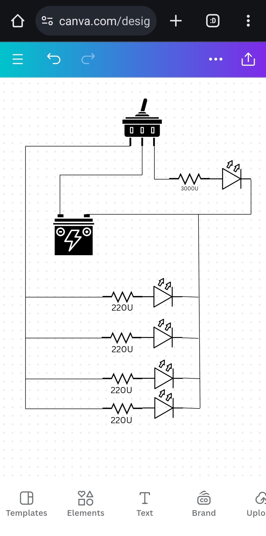
Something like this?
Also, are there any glaring issues with doing it like this?
Yep, the power source is a 7.5V wall wart
The lights are going to be on a wall, around 7' up, with the power running straight down to an outlet. About halfway up will be a switch
So the lone LED in the middle, with two resistors, is going to be on all the time, as a night light to the night light.
If the rest of the LEDs are on a switch, will I have to run two completely separate wires for the single LED, isolating it on its own circuit?
I'm tentatively planning on doing that, using heat shrink or something like that to tidy up the wires, then use two DC barrel jacks to connect each set of wires to the board. Are there any potential problems with this plan?

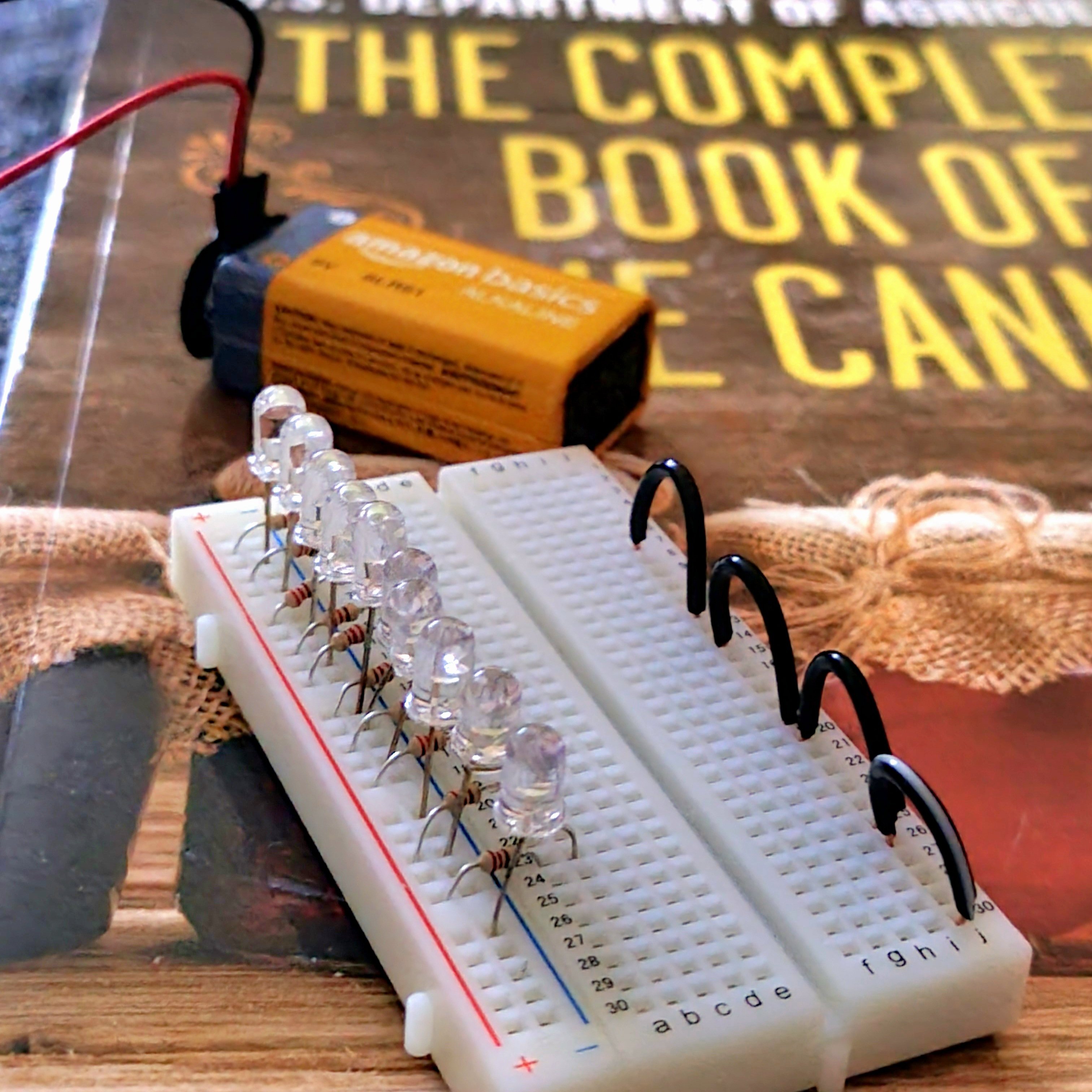
So after doing some analysis of human factors (asked my lovely wife what she prefers), I decided to ditch the PIR sensor and just go with a switch. This is just the current state of the board, I'm gonna rip apart an old router to get the barrel jack, then put this thing in an enclosure of some sort and call it day.
I'm also putting one LED with I think a 3k resistor that'll be on all the time as a night light to the night light, so you can find the switch

But if I want the LEDs to actually be bright, I probably need to use the sensor to activate a relay, right?


I know this is basic as shit, but I'm having a blast
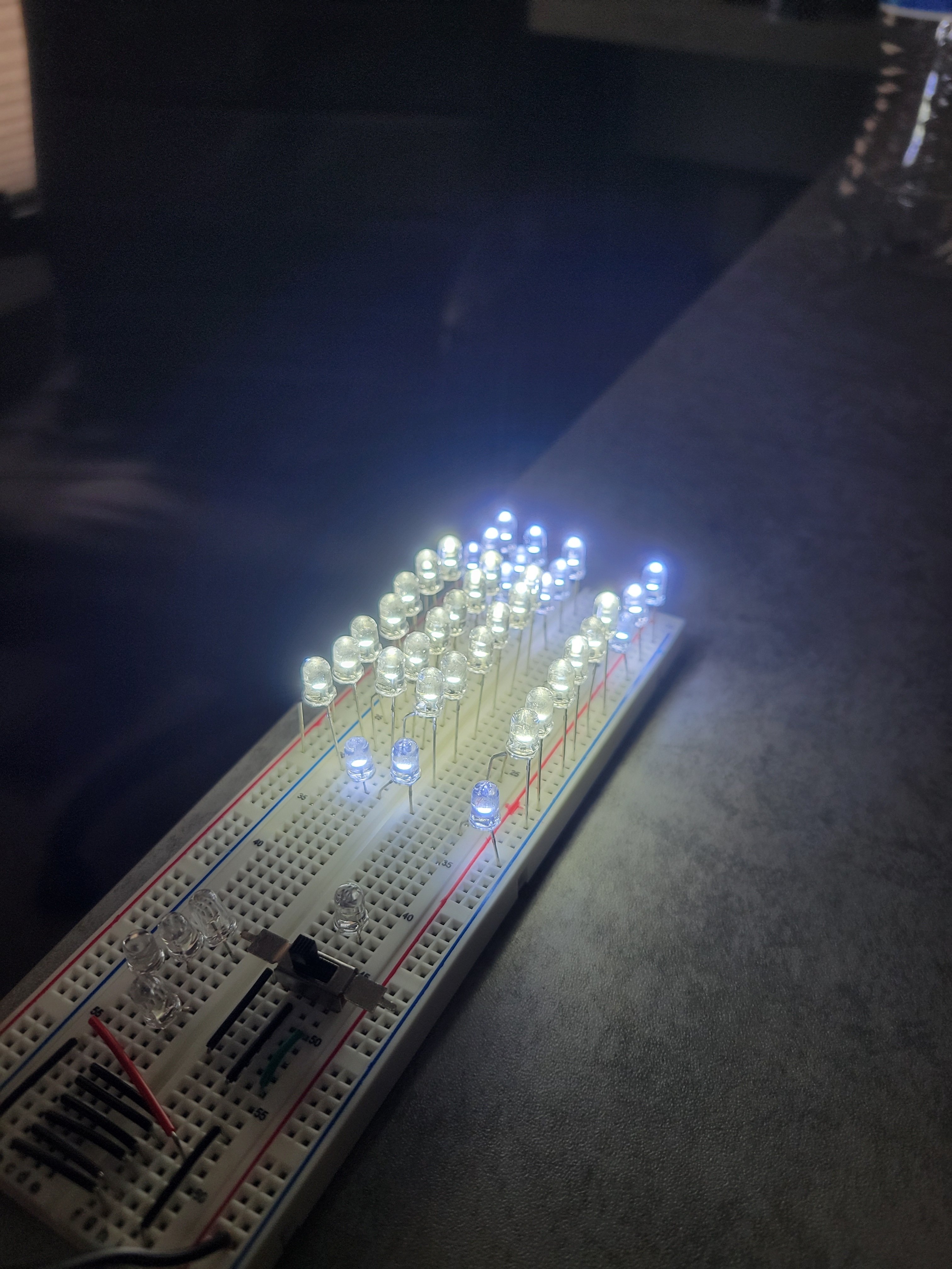
Update: first trial with the planned number of LEDs and pillow stuffing, looks fantastic!
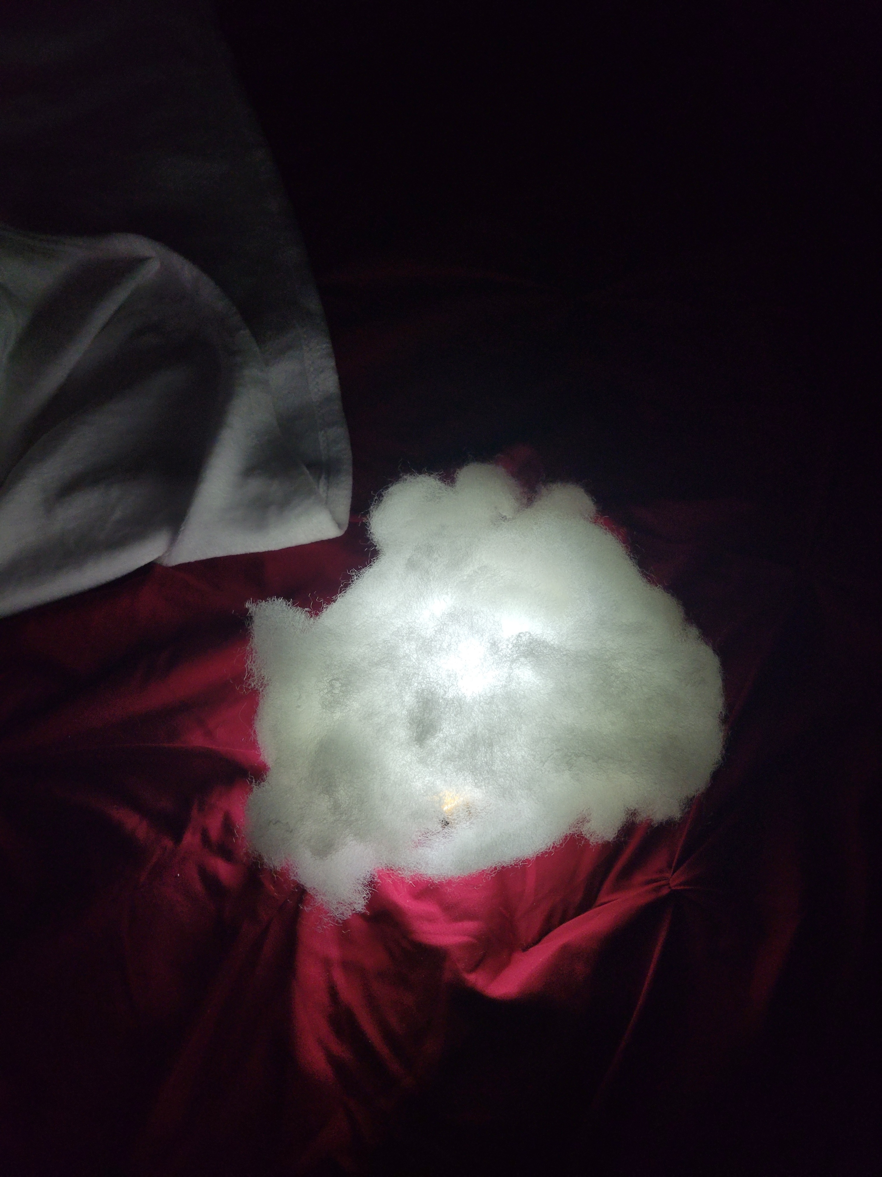
I've got the appropriate amount of light for my microscope ring light, but now I need to put it all in an enclosure of some sort.
If I don't have a custom board to solder these to, what are my best options for connecting these she mounting them into something?
If this is too vague, please let me know if I can clarify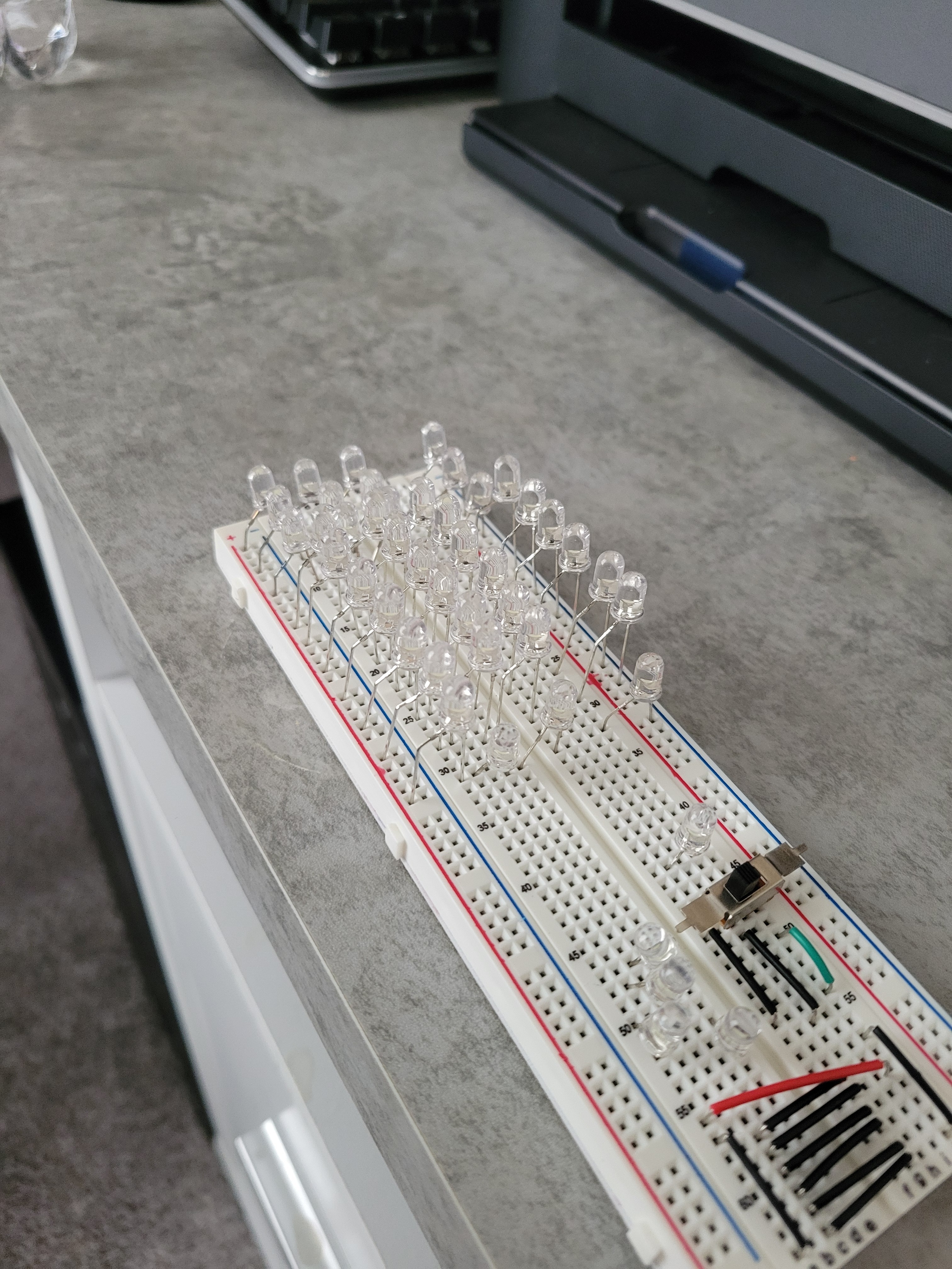
I got a microscope at auction a few weeks ago for a great price, only issue is the lights are super dim.
I decided to make some supplementary lighting for it, this was my first little proof-of-concept, to show myself that all the formulas I learned back in physics really work and that I can put together simple stuff without destroying any components, and while understanding what I'm doing.
Next will be to rerun the numbers with 5V from a wall wart, then maybe start working on a housing for everything. It's been years since I tinkered with electronics and I forgot how much fun it is, I'm having a blast!
That's about all really, I'm super excited about baby's first breadboard and I'm just happy to be here!
Also, if anyone sees something that is a safety hazard, please let me know
Also also: Technically these aren't the correct resistors, they're allowing ~26 milliamps across the LEDs, when they're rated for 20, but I'm here for a good time not a long time
You may or may not be interested to hear that I took your warning to heart and I'm now planning on using an actual DC power supply, coupled with either a resistive or inductive ballast which will also be designed for that purpose.
I'm sure the original plan is easily workable for someone with training or education, but for an amateur, it was too far outside the box to find reliable information and feel confident in it