this post was submitted on 30 Aug 2024
24 points (96.2% liked)

Ask Electronics

3258 readers
2 users here now

For questions about component-level electronic circuits, tools and equipment.

Rules

1: Be nice.

2: Be on-topic (eg: Electronic, not electrical).

3: No commercial stuff, buying, selling or valuations.

4: Be safe.


founded 1 year ago
MODERATORS
 

I asked a while ago, how to build an automatic light switch and finally got around to actually building it.

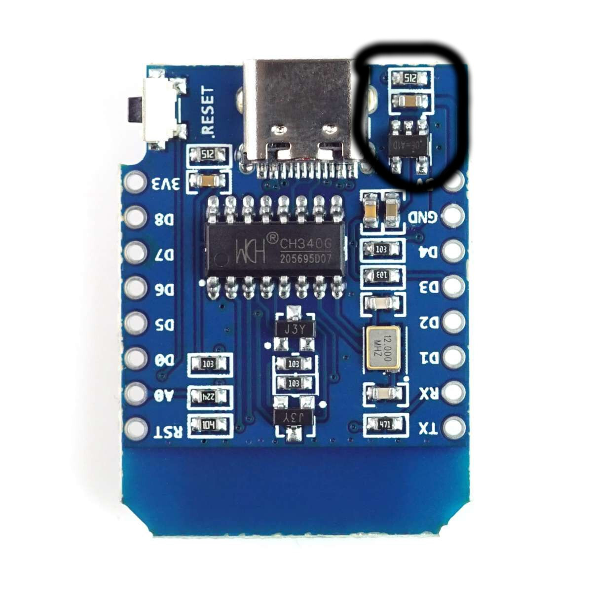
My board is an ESP8266 mini D, and ignoring all the sensor parts, my problem right now is powering the actual light.

It's just a small LED array and I connected it directly to the 5V and GND pins (controlled via a transistor).

Measuring from the wall (so including the PSU), this whole setup pulls about 3W (so far expected), however, one small component close to the USB connector gets uncomfortably warm, and I'm not sure, whether that's ok.

The hot component is one of the two small thingies circled in the picture. I thought the 5V get pulled directly from the USB plug, so I'm not sure, why there is any circuitry involved.

top 6 comments
sorted by: hot top controversial new old
[–] [email protected] 10 points 2 weeks ago* (last edited 2 weeks ago)

5V will be pulled directly from 5V supply

The chip you are concerned about getting warm I believe is your 3.3V regulator.

I would ensure your transistor has some resistors to ensure you are not drawing more current than required from the 3.3V supply

If that is all good then I will remind you of a few things

  1. The board you have is a clone (I use them... but they can be dubious)
  2. The ESP8266 requires a certain amount of current to run which will cause the chip in question to generate heat all on its own
  3. The chip in question appears to be an LDO which will mean going from 5v to 3.3v is done by turning the excess voltage into heat.

I couldn't find an exact Datasheet but I am led to believe that the chip is a clone of this

https://www.sunrom.com/download/670.pdf

Which I found on this store page

https://www.sunrom.com/p/rt9193-33gb-rt9193-33pb-sot23-5-300ma-ldo

And here is a wiki entry incase you are curious about Voltage Regulators and the such

https://en.wikipedia.org/wiki/Low-dropout_regulator

[–] [email protected] 7 points 2 weeks ago (1 children)

If I'm reading the part number right that regulator is rated for a current limit of 400mA At 5v that's 2 watts.

[–] [email protected] 2 points 2 weeks ago (1 children)

Two stupid questions:

1.) why is there a 5V regular for a USB plug that's supposed to be 5V only?

2.) will this regulator output more than 2W and burn itself out or is there a self limiting thingy? The 3W from the wall include power supply and board, so 2W don't seem too far off.

[–] [email protected] 5 points 2 weeks ago (1 children)
  1. It helps ensure that levels between 2.5v and 5.5v can be fed to the controller without breaking anything. For some cheaper power supplies you might get a voltage drop when starting to pull load, this will clean that up and prevent the voltage from dropping too low for the microcontroller.

  2. If I'm reading the correct datasheet I can see it is current limiting so it should shutdown when overdrawn.

[–] [email protected] 2 points 2 weeks ago

The voltage regulator is only used to generate the 3.3V supply for the ESP. But OP is using the 5V from the input of the regulator to power the LEDs.

At max it is wasting about 0.7W if the 400mA max current is right. But it will still get hot due to the current draw of the ESP. Even at half of the max. rated current this device is probably 30-40 degrees above your ambient temperature.

[–] [email protected] 2 points 2 weeks ago

I have never used an ESP but as far as I can tell, you are right. There is no component involved for the 5V. Some boards have a diode and a fuse between VBUS (5V USB) and the 5V rail on the board, but that is not the case for the board in your picture.

The black component with "512" is just a pull-down resistor for one of the CC lines of the USB connector. This should not get particularly warm.

The brownish thing is the input capacitor of the voltage regulator. It can get a little warm due to ripple currents, but I wouldn't expect a lot of heat.

Are you sure it is not the black 5-pin voltage regulator for the ESP? As far as I know those ESPs can be a bit power hungry depending on what you have enabled (e.g. WiFi).

Maybe you can check the temperature without your LED matrix connected and see if it is hot as well.